Visualize a Line of Sight in Blender
This is a simple how-to to create a dynamic line of sight visualization using Blender and Geometry Nodes.
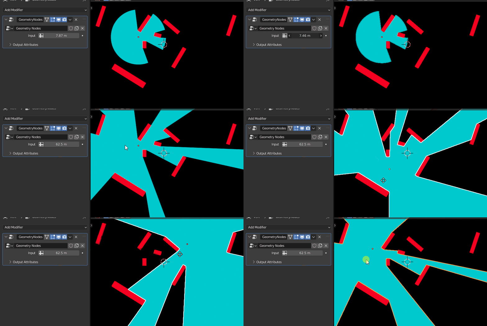
It can be useful to rapidly visualize line of sight obstacles or to have a very crude approximation of sound diffusion inside of a building.
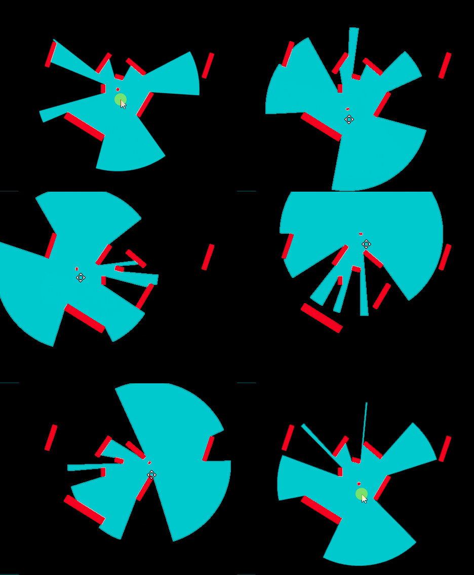
Here's what we're going to create :
This effect is achieved by instantiating a circle and throwing rays along the outer vertices. If the rays hit some geometry, the vertices will be displayed at the hit point position. Otherwise they will be displaced by a given value, until the maximal ray length is attained.
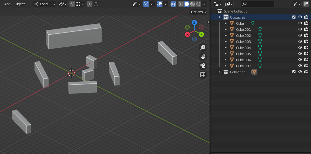
In a blank .blend file create a few obstacles and put them in a specific collection :
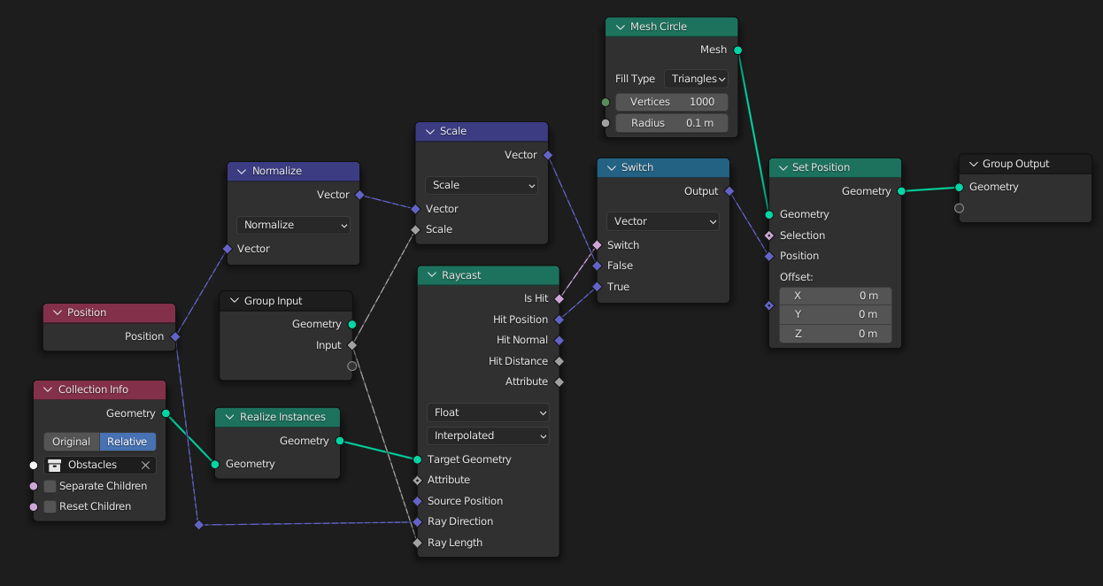
Create a new object and move it outside of the obstacles collection. Add a Geometry Node tree to the object and setup the nodes like so :
We're going to traverse the node tree from right to left, since this is basically how it is evaluated at runtime.
- Create a Set Position node.
- Plug its Geometry output into to the Group Output node, which should already be there when creating a new GN tree.
- Add a Mesh Circle node.
- Crank up the Vertices count to 1000 and lower the radius to a small value.
- Plug it into the Geometry input of the Set Position node.
- Add a Switch node which we will use to selectively push the circle vertices against the obstacles or the maximal radius if it doesn't hit an obstacle.
- Add a Raycast node. Plug the Is Hit output into the boolean input of the switch, and the Hit Position output into the True input of the switch. This will ensure the circle geometry is positioned exactly on the hit position if it ever hits an obstacles.
- Grab the obstacle collection with a Collection Info node. Set the instantiation mode to Relative.
- In order to use this geometry we need to Realize the Instances with a Realize Instances node. This will be our Target Geometry from the Raycast node.
- Add a new float input to the geometry node by dragging from the Group Input node's empty socket and linking it to the Ray Length input of the Raycast node. This will ensure we don't look for obstacles too far from origin.
- Add a Position node and plug it into the Ray Direction input of the Raycast node.
- Add a Vector Math node and set the operand to Scale.
- Add another Vector Math node and set the operand to Normalize.
- Plug the position into the normalizer, into the scale node, and finally into the False input of the Switch node.
- Plug the group float input into the Scale's scale input. This will ensure our circle outer vertices are pushed to the maximal ray length if they never hit an obstacle.
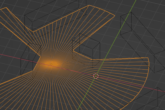
You can visualize what's going on under the hood if you lower the Mesh Circle node's vertices count, set the Fill Type to Triangle, and go into Wireframe mode.
Add some different shaders to the line of sight object and the obstacles to better differentiate them.
In the object's modifier properties, play with the input value to increase or lower the maximal ray length :
