BlenderBIM Add-on/BlenderBIM Add-on exporting 2D documentation
Please remove this "BlenderBIM_Addon_Documentation" template.
2D Construction Documentation[edit]
Although still in early alpha development, the BlenderBIM add-on provides the capability to publish a complete traditional 2D construction documentation of your model. The result is currently a combination of vector and raster data, compiled into SVG sheet files. (the projected geometry is rendered as a raster image, the cut geometry and any 2D annotations are kept as vectors)
There is one fundamental difference to the way traditional software handles 2D documentation. The 2D vector output from BlenderBIM add-on is not a finished fixed vector image, but as per definition of SVG a set of 2D geometry with applied CSS styling. That means, that in theory we can output one set of drawings and only by changing the applied CSS we can control the LOD.
The SVG sheet file is compiled from a SVG sheet template and one or more views exported from Blender, interpreting any variables included in the template and/or view.
The resulting SVG sheets can be easily converted into pdf files for presentation or dxf for collaboration. Examples of available converters:
Setting up a view[edit]
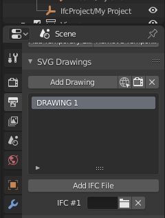
A view is basically an orthographic camera, which you can place manually, or by using the "Add Drawing" button in Output Properties > SVG Drawings. This command creates the necessary camera with a default name, centered on origin. The newly created camera is automatically activated and you can rename it by double clicking its name.
You can also activate any camera used as a view by selecting it from the list and using the "Activate View" command.
Selecting geometry to be cut[edit]
The raster image is rendered directly from your Blender model. The vector section is however not performed on the Blender geometry, but on an external IFC file.
How to export an IFC file from Blender.
The ifc file on which the vector cut will be performed has to be chosen under Output Properties > SVG Drawings > Add IFC File and selecting one or more IFC files.
Defining drawing appearance[edit]
As mentioned earlier, the resulting SVG file gets its final appearance from the style sheet, defined in the Project data directory. The CSS controls the appearance using classes, which means that by assigning an arbitrary class, any group of objects can be assigned a specific appearance. Some of the classes are defined as an example in the PROJECT_DATA_DIRECTORY⁄styles⁄default.CSS, defining the appearance of the annotation elements added through UI (see below) and some basic material hatches.
The symbols and hatches referenced by the CSS file are standard SVG files stored in PROJECT_DATA_DIRECTORY⁄templates⁄
The predefined material classes are assigned automatically to all objects, based on the name of their Blender material. As an example, when no material is defined, the section hatch in SVG is the default black. By assigning a material named named brick (case sensitive!) to an object, its resulting hatch in SVG changes in two parallel diagonal lines. Note that it is's blender material name if your object's material is IfcMaterial. If it's not IfcMaterial (for example if it's IfcMaterialLayerSet) then brick should be IfcMaterialLayerSet's name.
There are more patterns for materials you can find in blenderbim\bim\data\assets\patterns.svg that comes with BlenderBIM. Patterns like crosshatch1, crosshatch2, crosshatch3, sand, grass, etc. You can also define your own patterns in the similar manner.
Adding annotation[edit]
There are currently two ways to add annotation. First, the BlenderBIM plug-in recognizes a number of appropriately named objects on view export and interprets them as 2D annotation and second, it also recognizes the annotation added by the MeasureIt-ARCH plug-in. (currently only in the latest git master branch, see MeasureIt_ARCH readme for more information on how to make it work with BlenderBIM)
Currently recognized objects with their respective necessary names are:
- Curve - IfcAnnotation/Dimension.Number - as a dimension
- Curve - IfcAnnotation/Equal.Number - as a dimension with the letters EQ instead of its value
- Curve - IfcAnnotation/Leader.Number - as a label with a leader arrow symbol
- Curve - IfcAnnotation/Stair.Number - as a staircase arrow symbol
- Curve - IfcAnnotation/Section Level - as a section elevation dimension with an arrow symbol
- Curve - IfcAnnotation/Plan Level - as plan elevation dimension with a crosshair symbol
- Mesh - IfcAnnotation/Hidden.Number - as a dashed curve
- Text - IfcAnnotation/Text.Number - as a text field
- Curve - IfcAnnotation/Fall - indicate slope on a ramp, for example
The plug-in provides commands to create the correctly named dummy object in the Sidebar ("N" panel) > BlenderBIM > Annotation.
Dimensions[edit]
- Override a dimension
- Set the Description attribute of that dimension. This means that that dimension needs to be separate from other dimensions.
- Add BBIM_Dimension pset and enable "DescriptionOnly". Otherwise the description is shown in addition, instead of replacing the dimension.
Intelligent Tagging of Objects[edit]
Go here for adding labels, like wall/window tags, that are intelligently linked to the object's data.
To tag objects:
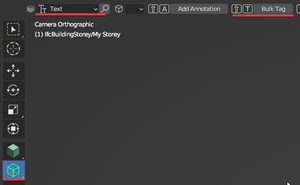
- select Annotation Tool choose annotation type
- select objects to tag
- use "Bulk Tag"
If you moved the tagged objects or changed them (for example stair is wider now) you can readjust tags by selection annotations and using "Readjust" in Annotation Tool.
Currently there are 2 ways of tagging:
- Text tagging - will create IfcAnnotation of type Text at the center of the object then you can refer to the tagged object properties in the text. More.
- Stair Arrow tagging - will create stair arrow by the stair X axis going until the last stair step. Example.
Drawing Styles and Filters[edit]
If you select the camera object of the drawing, and go to EPset_Drawing property you can set the following property values
- Metadata:
- For example add property you'd like to be exported to SVG class. Examples
Pset_WallCommon.Statusr"Pset_.*Common"- Will attach a class like the following to the SVG object
rPsetCommon-StatusEXISTINGDEMOLISHid68585- Example of how a css regular expression to style the svg
[class*="PsetCommon-StatusEXISTINGDEMOLISH"] { fill: url(#demolish); stroke: red; stroke-dasharray: 2, 1; }
- Example of how a css regular expression to style the svg
- Will attach a class like the following to the SVG object
- For example add property you'd like to be exported to SVG class. Examples
NOTE: currently attaching metadata is not supported for 2d representations and it's not possible to create custom style for them. See example, related issue to track progress
- Include and Exclude
- In the Include and Exclude property you can indicate what to include/exclude from the drawing. A few examples.
- Exclude:
IfcElement , /Pset_.*Common/.Status=DEMOLISHIfcElement , /Pset_.*Common/.Status=NEWIfcElement , EPset_Status.Status=DEMOLISH
- Include:
IfcElement , /Pset_.*Common/.Status=DEMOLISHonly show demo.IfcElement , /Pset_.*Common/.Status=NEWonly show new.
- Exclude:
- In the Include and Exclude property you can indicate what to include/exclude from the drawing. A few examples.
- Paths to...
- Stylesheet:
- defaults to:
drawings/assets/default.css
- defaults to:
- Markers:
- defaults to:
drawings/assets/markers.svg
- defaults to:
- Symbols:
- defaults to:
drawings/assets/symbols.svg
- defaults to:
- Patterns:
- defaults to:
drawings/assets/patterns.svg
- defaults to:
- ShadingStyles:
- defaults to:
drawings/assets/shading_styles.json
- defaults to:
- Stylesheet:
- Dimension Rounding
- MetricPrecision:
- ImperialPrecision:
- Example:
1/2rounds to the nearest 1/2"
- Example:
- JoinCriteria
- If no JoinCriteria is given, it defaults to unjoin the following things
["class", "material.Name", 'r"Pset.*Common"."Status"']. If you want to unjoin justmaterial.Name, for example, set JoinCriteria value to:material.Name
- If no JoinCriteria is given, it defaults to unjoin the following things
Text Styling[edit]
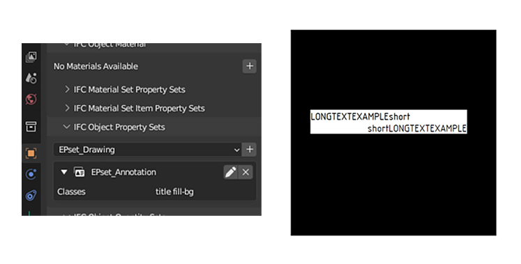
- Background for Ifc Text annotations in SVG
To add fill background of Ifc Text annotation with white color you can add "fill-bg" class to EPset_Annotation.
Exporting a view[edit]
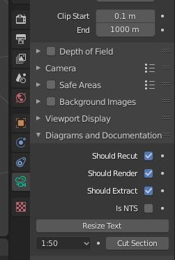
To export a view, select the proper camera, go to Object Data Properties > Diagrams and Documentation > Cut section. On running the "Cut section" command a SVG file is generated in the Diagrams folder in your Data Directory. The contents of the generated SVG file depend on the options you check in the Diagrams and Documentation section:
- Should Recut - a vector image is generated by intersecting a plane parallel to the camera plane in camera origin with geometry of the ifc files selected in Output Properties > Documentation.
- Should Render - a raster image is generated by rendering the current Blender model with the current camera
- Should Extract - metadata from the IFC file, such as material or property data (such as in smart annotations), are re-extracted
Creating schedules and adding them to a sheet[edit]
Using IFCCSV https://wiki.osarch.org/index.php?title=BlenderBIM_Add-on/BlenderBIM_IFCCSV
Background SVG[edit]
Background SVG's: https://github.com/IfcOpenShell/IfcOpenShell/issues/3002#issuecomment-1518668495
Copying Annotation from one drawing to another[edit]
https://github.com/IfcOpenShell/IfcOpenShell/issues/2966#issuecomment-1606914228
Settings in Blender Preferences - Add-ons[edit]
- SVG Command:
See also[edit]
Updating from older Drawing System[edit]
https://github.com/IfcOpenShell/IfcOpenShell/issues/2978#issuecomment-1510374693
External Resources[edit]
Tutorial & Examples
- Creating drawings - BlenderBIM Add-on 200912 Technical WIP Demo - September 12, 2020
- IFC OpenBIM SVG construction documentation - 200620 BlenderBIM Add-on Technical WIP Demo - June 23, 2020
- Housing alteration design documentation with BlenderBIM Add-on
- The Revit office building as pure IFC documentation
- Examples of floor plans derived from IFC
