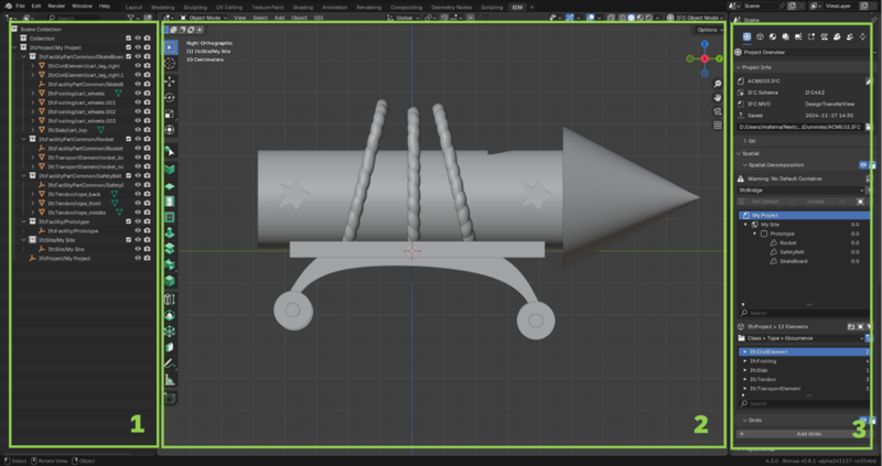
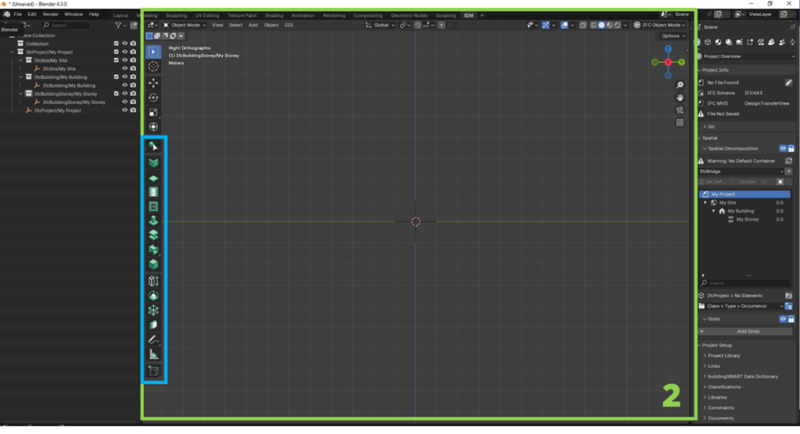
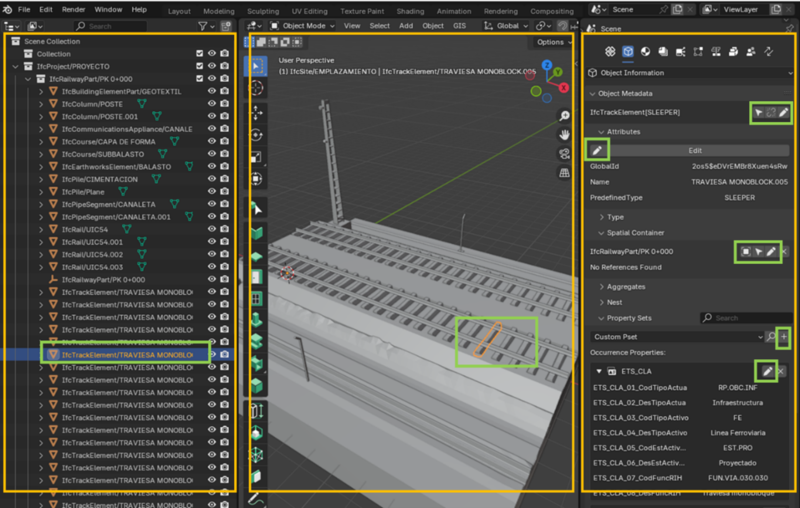
The Bonsai interface is organized into three main areas, each with a specific function. These areas work together seamlessly to provide a complete environment for the design, editing, and management of IFC models.
Zone 1: IFC Entity Tree (Left Panel)
The IFC Entity Tree displays a hierarchical list of all the IFC entities in your model. From this panel, you can explore and select any part of the model to edit. If you cannot find an element in the model, use the search function to locate it quickly.
Zone 2: 3D Geometry Visualization (Central Area)
The IFC model is displayed in 3D in this area, allowing you to manipulate and analyze it. You can rotate, zoom, and select elements to inspect them from different perspectives. Using keyboard shortcuts, such as holding Shift to rotate faster, helps improve navigation within the model.
Zona 3: Non-Graphical Data of the 3D Model (Right Panel)
This panel provides access to the non-graphical information of the model to ensure proper documentation. The information is organized into tabs that group various essential data sets related to the model. Below is an overview of each tab:
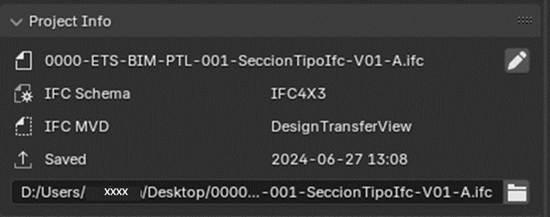
**Project Overview** tab provides general project information in a centralized view, reducing the need for multiple tools. It serves as a reference point for understanding the overall context of the IFC model.
Main functions:
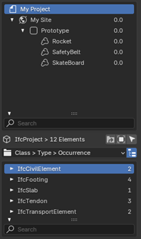
- **Project Info:** Allows you to view general project information, such as the project name, author, and other key details that, while not the most exciting, are essential for keeping the model organized and making navigation easier.- **Spacial Decomposition:** Provides a structured map of the IFC model, allowing you to visualize and organize elements based on their spatial location within the project.- **Property Sets (Pset) Templates:** Enables the creation of templates for Property Sets to be used for each model element, simplifying the process of assigning attributes to elements.
- **Georeferencing:** Configures the model's geographic location to ensure it is accurately placed in the real world.
- **Model Element Filtering:** Allows advanced filtering criteria to search and organize elements in large models, making it easier to find and organize elements efficiently.
- **Model Federation:** Enables the integration of multiple IFC models into a single workspace, ensuring proper coordination between different models and data sources.
- **buildingSMART Data Dictionary:** Provides access to a standardized dictionary that defines terms and attributes, ensuring everyone works with the same BIM language.
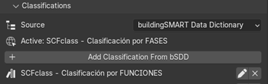
- **Classifications:** Activates classifications for model elements, helping with organization and preventing confusion when identifying different element types (e.g., a wall versus a door).
Object Information tab allows you to manage all the details of each element in the IFC model. You can access key information about each object and control everything related to its structure and properties. Main functions:
Element Data: Provides all the information about each object, such as its IFC class, indicating the type of entity (wall, window, column, etc.). It’s like having a detailed record of each element.
Property Sets (Pset): Property Sets are detailed characteristics of each object, such as dimensions or technical specifications. This tool allows you to customize the model based on the project needs.
Quantity Sets: Quantity Sets provide information about the material used in the model, allowing you to make precise measurements for material estimations. In summary, Object Information is where you manage and access all the crucial information for each element in the model, enabling full control and easy adjustments or verifications.
Geometry and Materials tab allows you to manage both the geometry of model elements and their material properties. Here, you can modify the size, shape, and position of elements, as well as adjust their physical characteristics such as textures, colors, and technical properties (e.g., density or thermal conductivity). This tab also provides tools for working with parametric models, enabling precise adjustments and element replication.
Main functions:
Geometry: Allows you to change the size, shape, and position of any element. You can adjust details like moving a column to a different location.
Parametrization: For parametric models, this tool enables precise adjustments of dimensions or the duplication of elements quickly.
Materials: Assign materials with textures, colors, and physical properties. You can define whether walls are rough or shiny, or whether the roof reflects light. Technical properties like density (weight) or thermal conductivity (ability to retain heat) can also be defined.
Drawings and Documents tab allows you to generate plans, drawings, and documents from the 3D model. Here, you can create 2D plans with different views, customize their details, and export them to common formats. Below are the main features:
Create Drawings: Generate 2D plans from your 3D model, including sections, floor plans, elevations, and sections. You can customize aspects like scale, levels of detail, line thickness, and colors.
Annotate and Label: Add dimensions, labels, and explanatory notes to the plans to detail dimensions, materials, and other important project aspects.
Generate Documents: Export plans to formats like PDF or DWG for sharing with your team. You can also customize the plans with your logo, headers, and title blocks, and organize plans into sets ready for printing or sending to the client.
Services and Systemstab allows you to manage all technical building systems that are not part of the main structure but are essential for its operation, such as electricity, plumbing, heating, ventilation, and security systems.Below are the main features:
Definition and management of systems: Create and organize technical systems such as electricity, HVAC (heating, ventilation, and air conditioning), plumbing, and fire alarms. Each system can have specific properties to ensure proper integration into the building design.
Equipment and device assignment: Insert and configure the equipment required for system functionality, such as fans, pumps, sockets, and thermostats. Verify the specifications of each device to ensure compatibility and optimal placement.
Structural Analysistab allows you to define and analyze the structural conditions of an IFC model, ensuring its stability against various loads and external forces.
Main Features:
Define loads and forces: Configure the loads the building must withstand, including the weight of occupants, furniture, wind, snow, and seismic events. Assign these loads to structural elements such as beams and columns.
Define boundary conditions: Specify the building’s interactions with its environment by defining constraints and support points that affect its structural behavior.
Facility Management tab allows you to plan and organize the maintenance of building systems and equipment, ensuring their proper operation over time.
Main Features:
Maintenance management: Schedule and manage inspections and repairs for various building systems and equipment. Define the frequency of maintenance tasks to ensure efficient and safe operations.
Asset and inventory management: Track building equipment and installations while maintaining an up-to-date inventory of spare parts and materials required for maintenance.
Quality and Coordination tab provides essential tools for optimizing and analyzing IFC models. It streamlines conflict detection, data integration, and model refinement to enhance overall project quality and functionality.
Main Features:
Model refinement: Clean and organize the IFC model to improve efficiency and handling.
Automation tools: Small utilities for element extraction, data retrieval, and model merging.
Clash Detection: Identify and manage conflicts between elements to avoid construction issues.
BCF file management: Simplify problem tracking and resolution through efficient exchange of comments and annotations.
EXPLORING AN IFC
(Details on how to start with an IFC model)
DESIGN AND EDITING OF IFC
BASIC DESIGN TOOLS
Exploring Bonsai Dropdown Menu
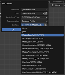
In section 2 of the interface, you will find a dropdown menu containing a series of icons. Each icon represents a predefined IfcElementType, such as walls, windows, or other construction elements. These elements serve as the basis for design: by assigning them a geometric shape, they automatically become the selected IfcElement.
This menu is primarily focused on building elements, but it also allows for the creation of generic elements.
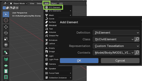
Creating Generic Elements
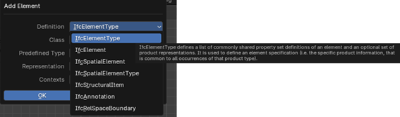
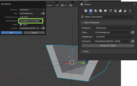
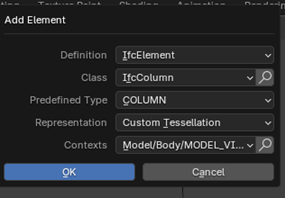
Go to the Definition section. Here, you will select the entities that will classify your object.
If you have doubts about an entity, hover the cursor over it to see a brief description.
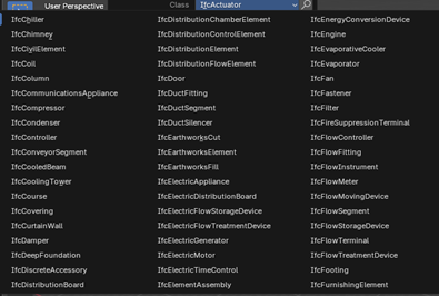
In the Class section, you will classify your object within the selected entities. The options are listed alphabetically for easier searching.
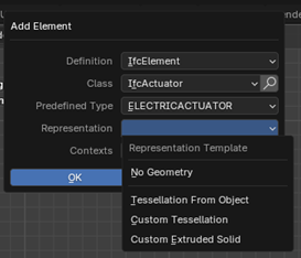
In the Representation section, you will define how your object will be visualized. The available options are:
No Geometry: The object will have no graphical representation. Suitable for purely informational elements.
Tessellation From Object: Uses an object created in Blender. Ideal for custom designs, such as beams, gutters, or walls with complex shapes.
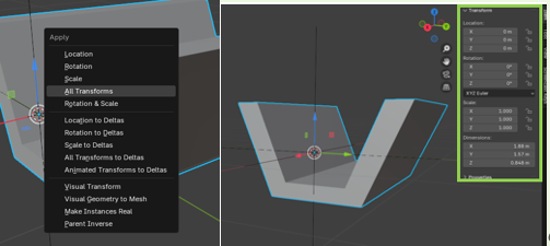
Tip: After modifying your object in Blender, press Ctrl+A and select Apply All Transforms to avoid future issues.
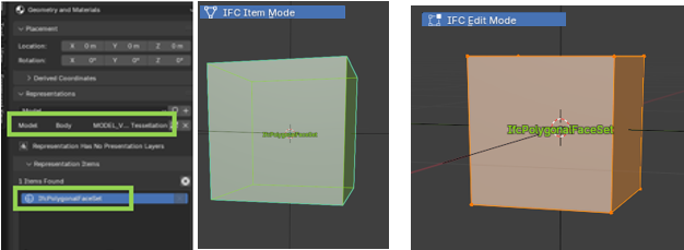
Custom Tessellation: Allows for advanced and customized representation.
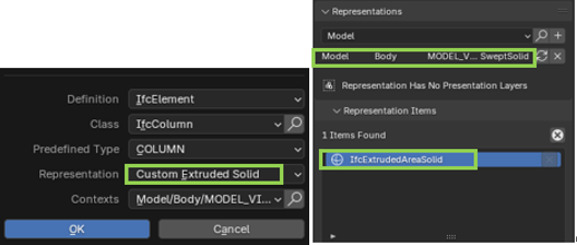
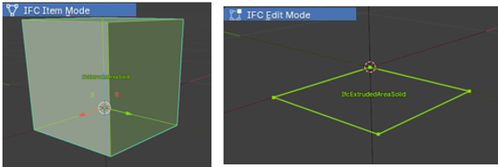
Custom Extruded Solid: Recommended for linear shapes that require extrusion.
In the Contexts section, you will define the context in which your object will be used. This step completes the model definition process.
For a better understanding of how to use this tool, it is recommended to watch this video, which clearly explains how to create a building: Watch video.
Modifying Data and Elements in Bonsai
Sometimes, it is necessary to modify the data of elements. This may be due to errors, design changes, or simply personal preference. Bonsai allows these modifications to be made easily.
Modifying data
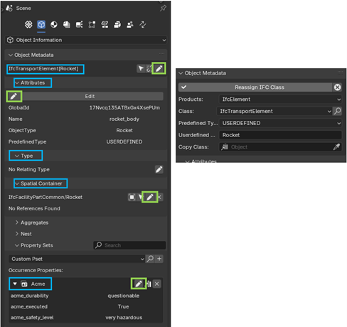
From the Object Information tab, in the Object Metadata dropdown, the following actions can be performed:
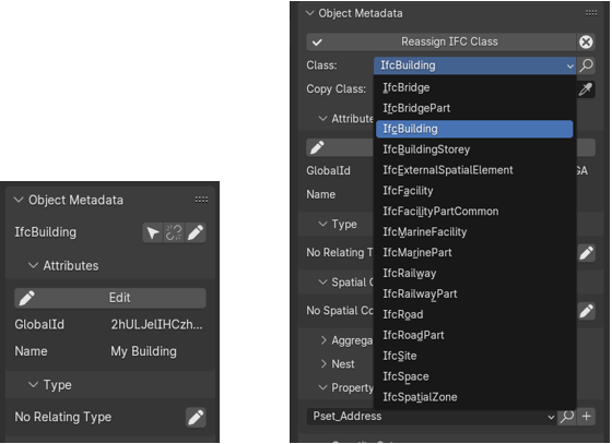
Reassign IFC classification: Change the IFC classification of an element.
Modify attributes such as name or type: Update the name or type of the element to improve its identification.
Change its spatial container: Move the element to another level or section of the project using Spatial Container.
Edit user-generated Psets: Adjust previously created custom data. This topic will be covered in more detail later.
Modifying Position
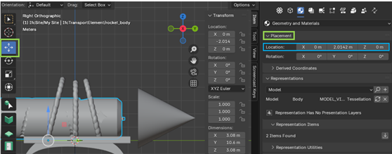
Go to the Geometry and Materials tab.
In the Placement dropdown, adjust the position or rotation of the object.
For a visual approach, use Blender’s Gizmo to move the object. Ensure the changes are reflected in the Placement dropdown; otherwise, the changes will not be saved.
Modifying Geometry
Select the object you want to modify.
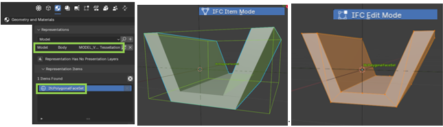
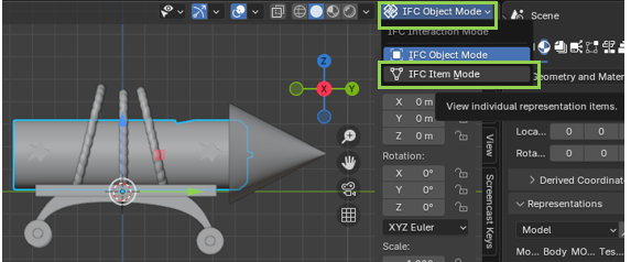
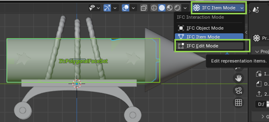
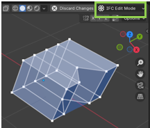
Go to the IFC Object Mode dropdown and select IFC Item Mode.
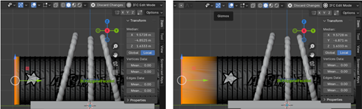
Select the object again and, in the same dropdown, choose IFC Edit Mode.
You are now ready to edit the geometry.
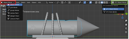
Tip: Always edit in IFC Object Mode, not in Blender’s standard editor.
Creating Openings in Your Designs
If you need to add openings, such as doors, connections between floors, or drains in slabs, follow these steps to create them accurately.
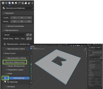
Option 1: Creating Voids
Create an Opening Element:
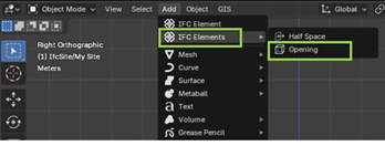
Go to: Menu > Add > Ifc Element > Opening. This generates an empty element in your design, which will serve as the mold for the opening.
Adjust the mold to your needs:
Edit the shape of the Opening as if it were an IFC object (i.e., define its size and shape precisely). It can be round, square, or any other required shape.
Integrate the opening into your design:
First, select the object where you want to create the opening (e.g., a slab, wall, etc.).
Then, select the Opening Element (the void you created).
Go to the Geometry and Materials tab, open the Geometric Relationships dropdown, and click on Voids > Add Opening.
The opening is now correctly integrated into the design.
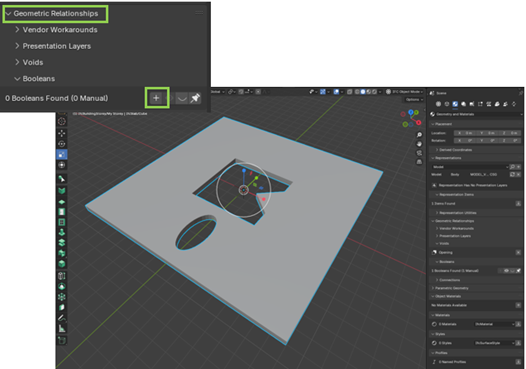
Option 2: Boolean Method
For a more manual approach, you can use Boolean method to create openings.
1. Create the object that will serve as the cutter: Design a cylinder, cube, or any shape you need for the opening in Blender. This object will act as the cutter.
Select the objects: First, select the cutter object. Then, select the object where you want to create the opening (e.g., a wall, slab, etc.).
Perform the Boolean operation: Go to the Geometry and Materials tab. Open the Geometric Relationships dropdown and select Booleans > Add.
The opening is now created with precision.
Pset: Add, modify, or delete Property Set
What are Psets?
Psets, or Property Sets, are collections of data associated with the elements of your model. They do not refer to geometric properties (such as shapes or dimensions) but rather to the characteristics that describe how elements behave or their specific specifications.
Types of Property Sets in IFC
Property Sets in IFC are generally grouped into two categories:
1. **Standard Psets**: Defined by IFC standards and widely accepted in the AEC industry. Examples include:
- **Pset_WallCommon** (for walls).
- **Pset_WindowCommon** (for windows).
- **Pset_SpaceOccupancyRequirements** (for space occupancy requirements).
Custom Psets: Created specifically for a project or organization to meet particular needs. These are tailored to unique requirements and are not part of the standard IFC definitions.
**Purpose of Psets**
Psets serve two primary purposes:
Standardization: They ensure that all projects follow the same logic and structure, promoting consistency across designs.
Ease of Analysis: They allow for efficient filtering and analysis of specific elements. Without custom Psets, navigating through data would be like searching for a needle in a haystack.
Adding Custom Psets to Your Model
To include user-defined Psets (Property Sets) in your model, follow these steps:
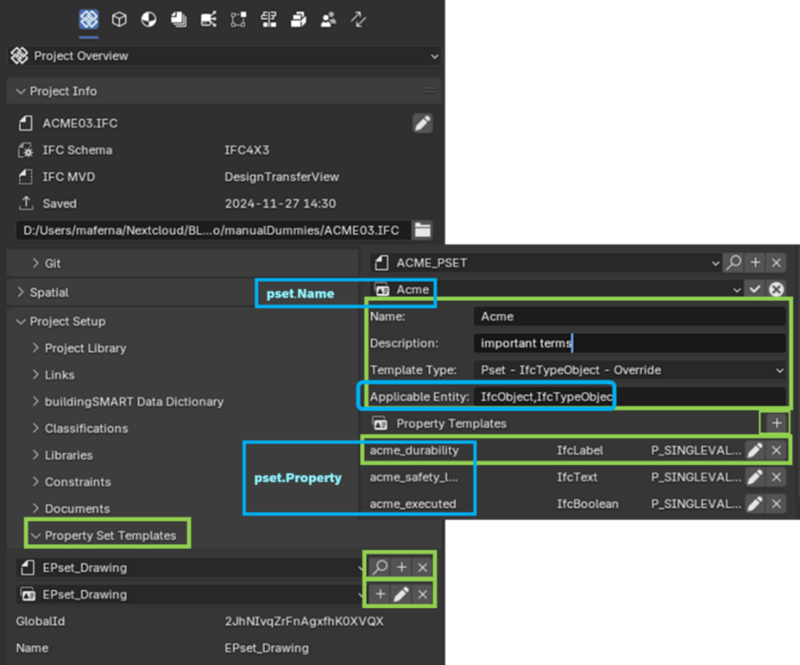
**Step 1: Create a Property Set Template**
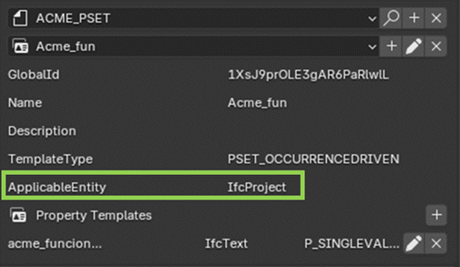
1. Navigate to the **Property Set Templates** tab.2. Create a template for custom Property Sets (Psets) to tailor them to specific user or project requirements.
Step 2: Define Applicable Entities
Specify the entity to which the Pset applies using the ApplicableEntity field. For example, if the Pset is relevant to the entire project, indicate this in the field.Step 3: Save Custom Properties
Custom properties must be saved in the following directory:
C:\Users\usuario\AppData\Roaming\Blender Foundation\Blender\4.2\extensions.local\lib\python3.11\site-packages\bonsai\bim\data\pset
These properties can be reused in other projects that require them.
Additional Resources
For further guidance, refer to this tutorial:
Watch video
Adding Psets: Individually or in Bulk
Psets (Property Sets) can be added to your model either individually or in bulk, depending on your workflow and the stage of your project.
Adding Psets Individually
If you are modeling from scratch and prefer a meticulous, step-by-step approach, you can add Psets to each element individually. Follow these steps:
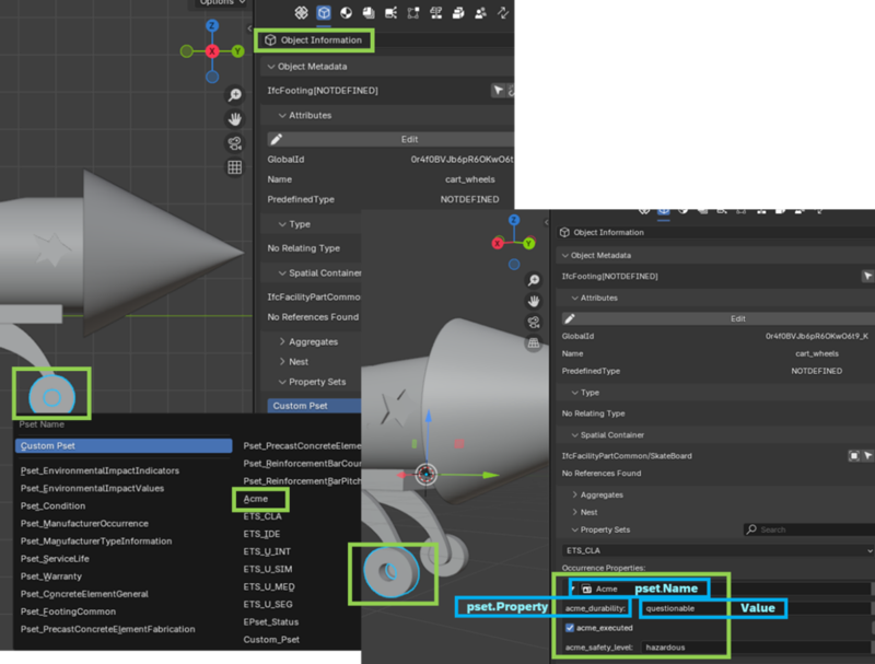
Go to the Object Information tab.
Open the Property Sets dropdown.
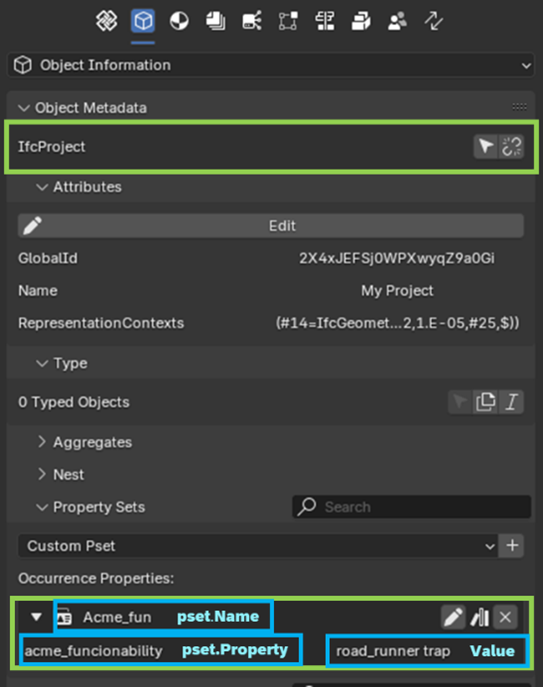
Under Custom Pset, select the template you previously created.
Fill in the values for the properties included in your template.
This method is ideal for detailed work or when your model is still in its early stages. It works the same way for the IfcProject entity.
Adding Psets in Bulk
For projects with hundreds of similar elements, the bulk method saves time and effort. Here’s how to do it:
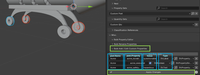
Go to the Object Information tab.
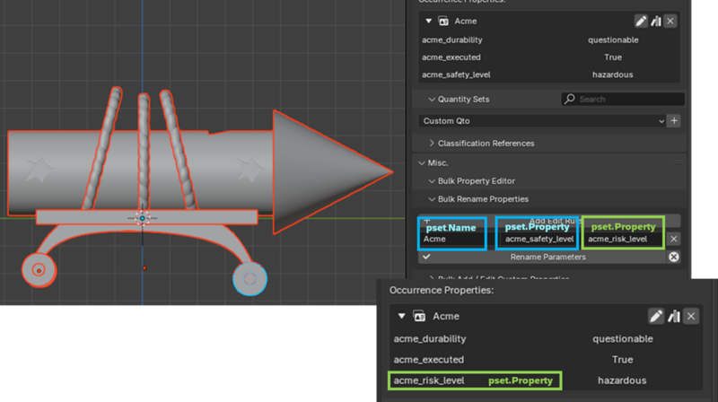
Navigate to the Misc. (miscellaneous) dropdown and select Bulk Property Editor.
From here, you can:
Rename properties: Change the names of properties without altering their values.
Add or edit properties: Enter the Pset name, property, and value. Ensure you specify the entity type used in your template.
Remove properties: Delete properties that are no longer needed.
Select all the objects to which you want to apply these changes.
Click on Apply Changes. The changes will be applied to all selected objects.
Important Notes
Editing Properties: When editing properties, the object will only retain the properties you list. If you include only one property, the rest will be removed. Ensure you include all necessary properties to avoid data loss.
Renaming vs. Editing: Renaming only changes the name of the property. To edit values, use the Edit function. Properly managing your Psets will ensure the accuracy and integrity of your model.
IFC MANAGEMENT
(Re)Organizing the Model
A well-structured IFC schema is a cornerstone of effective Building Information Modeling (BIM). It ensures that data is organized, consistent, and reusable across all stages of a project. Proper management of IFC schemas allows for:
Efficient data handling: Simplifies data management and reduces errors.
Improved collaboration: Ensures all stakeholders work with standardized and reliable data.
Enhanced project outcomes: Minimizes last-minute changes and supports better decision-making.
Working with Zone 1: Selecting and Editing Elements
The first step in managing your IFC model is to understand how to interact with elements in Zone 1. This zone is where you select and edit the two main types of elements in your model:
Containers:
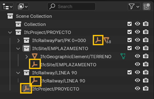
These are hierarchical elements that organize your model, such as IfcBuilding, IfcRailway, IfcBuildingStorey, and IfcRailwayPart.
To edit a container, select the null element (represented by the symbol of three connected bars). This allows you to modify properties or adjust its position within the hierarchy.
3D Objects:
**These are the physical components of your model, such as IfcDoor, IfcSlab, **IfcFooting’’’, and others.
To edit a 3D object, simply select it directly in the viewport or the object list.’''
Organizing and Refining Your Model in Zone 3
Once you have selected an element in Zone 1, you can further organize and refine it in Zone 3. This zone provides tools for managing the hierarchical structure and properties of your model.
Spatial Decomposition (Hierarchy Tree)
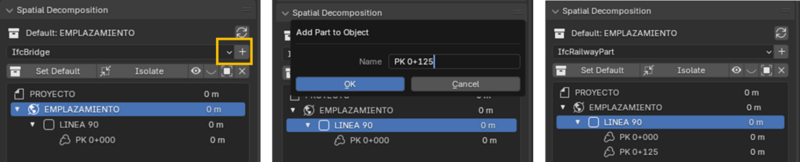
Navigate to Project Overview → Spatial Decomposition to access the hierarchical tree. This tree acts as an organizational chart for your model, allowing you to:
Add new levels: Useful if your project expands or requires additional subdivisions.
Remove unnecessary levels: Helps reduce clutter and streamline the model structure.
Changing Entity Types
If you need to modify the entity type of an element (e.g., changing a wall to a slab):
Go to Object Information → Object Metadata.
Select the element you want to edit.
Adjust its classification or rename it directly in the Attributes section. This ensures that elements are correctly labeled and categorized.
Editing 3D Objects
For 3D objects that are not correctly mapped or classified:
Select the “▽” symbol in Zone 1. This highlights the object in Zone 2.
In Zone 3, you can:
Assign the correct IFC class: Ensures the object is classified according to IFC standards.
Rename the object: Avoids generic or unclear naming conventions.
Place it in the appropriate level: Organizes the object within the hierarchy tree.
Add or adjust properties: Enhances the object’s metadata for better project management.
Best Practices for IFC Schema Management
To ensure your IFC schema remains consistent and effective:
Standardize naming conventions: Use clear and consistent names for all elements and properties.
Regularly review the hierarchy: Keep the spatial decomposition tree organized and up-to-date.
Validate data frequently: Use IFC validation tools to check for errors or inconsistencies.
Document changes: Maintain a log of modifications to track updates and ensure transparency.
Federating and Merging
(How to federate and merge IFC models)
Extracting Data and Elements
(How to extract data and elements from the model)
IFC SEMANTICS AND ENTITY REFERENCE
Introduction to IFC Semantics
The semantics of IFC refer to the meaning behind the entities, attributes, and relationships defined in the Industry Foundation Classes (IFC) schema. Unlike purely geometric formats, IFC describes not only shapes but also the purpose, function, and context of building elements. Each object belongs to a well-defined class (for example, IfcWall, IfcSpace, IfcDoor), carries properties (Psets), and participates in a spatial hierarchy (IfcProject → IfcSite → IfcBuilding → IfcBuildingStorey → elements).
Understanding IFC semantics is essential when working in Bonsai, because the software operates directly on the IFC data structure rather than converting it into a proprietary model. This implies that:
Each element has an explicit role within the model.
Entities follow the rules defined by the IFC standard (required attributes, relationships, hierarchy).
Certain operations are only available for specific classes of objects.
Bonsai uses IFC semantics to help maintain a coherent and standards-compliant model.
This section provides an overview of how IFC entities should be interpreted and how this understanding supports an OpenBIM workflow within Bonsai.
How Bonsai Interprets IFC Entities
Bonsai works directly with IFC files without translating them into an intermediate format. This means that the model’s structure — entities, relationships, properties, and the spatial hierarchy — is read as defined in the IFC schema and presented to the user for inspection and editing.
In general terms, Bonsai interprets IFC entities as follows:
Spatial Structure: Bonsai respects the IFC spatial hierarchy (IfcProject, IfcSite, IfcBuilding, IfcBuildingStorey, IfcSpace), allowing users to reorganize the model while maintaining standards compliance.
Entity Classes: The software identifies the IFC class of each object and exposes editing options appropriate for that class, such as data, geometry, location, or properties.
Property Sets: Bonsai displays and allows editing of Psets, including both native IFC property sets and user-defined ones.
IFC Relation*
Common IFC Entities and Concepts
This section introduces some of the most frequently used IFC entities and concepts within Bonsai. Understanding these elements helps users interpret the structure of an IFC model, edit it correctly, and maintain OpenBIM compliance. Each subsection provides a clear explanation of the entity or concept, its purpose within the IFC schema, and how it relates to typical workflows in Bonsai.
IfcElementType and IfcElement
Understanding the distinction between IfcElementType and IfcElement is essential for working with IFC models. These two concepts separate the definition of an element type from the actual instance used in a project.
IfcElementType
Definition: An IfcElementType is a template or generic definition of an element. It describes the common properties and behaviour of a type of element but does not represent a specific instance in a project.
Purpose: It defines the general characteristics of an element type, such as a wall, window, or door. For example, an IfcWallType can define the common properties of all walls of a certain type (dimensions, materials, etc.).
Usage: It is used to create specific instances of elements (IfcElement) in a project. In other words, an IfcElementType acts as a “mold” that can be reused multiple times.
Example: An IfcWindowType can define a window type with standard dimensions and a given material. This type may then be used to create multiple IfcWindow instances in a building.
IfcElement
Definition: An IfcElement is a specific instance of an element in a project. It represents a real and concrete object within a BIM model.
Purpose: It defines the geometry, placement, and individual properties of an element in a specific context. For example, a particular window placed in a specific wall.
Usage: It is created from an IfcElementType, inheriting its general properties, while also allowing additional instance-specific information.
Example: An IfcWindow created from an IfcWindowType may have a specific location in a wall, adjusted dimensions, and unique attributes such as an identifier or cost.
**Relationship between IfcElementType and IfcElement **
An IfcElementType is a generic definition, while an IfcElement is a specific instance created from that definition.
The IfcElementType provides shared properties, and the IfcElement represents the actual real-world object inside the BIM model.
** Summary Table **
Characteristic
IfcElementType
IfcElement
Nature
Template or generic definition
Specific instance in a project
Purpose
Defines common properties of an element type
Represents a real object in the BIM model
Example
IfcWallType (a wall type)
IfcWall (a specific wall in a building)
Relationship
Basis for creating IfcElement
Derived from an IfcElementType
** Practical Example **
IfcWallType: Defines a wall type with a thickness of 20 cm and concrete as the material.
IfcWall: A specific wall in a building, based on the IfcWallType but with its own length, placement, and identifier.
IfcSpace
Definition: An IfcSpace represents a bounded area within a building that can be used for analysis, occupancy, or spatial organization. It is a semantic object, not necessarily a physical wall-bounded volume, and can contain information about function, area, volume, or zoning.
Purpose: IfcSpace is used to define rooms, zones, or functional areas within a building. It allows the BIM model to manage occupancy, energy calculations, HVAC planning, and spatial relationships.
Usage in Bonsai:
IfcMaterial
Definition: An IfcMaterial represents a substance used to construct building elements. It can be defined alone or linked to elements via associations like IfcRelAssociatesMaterial.
Purpose: Materials define physical characteristics of building elements, such as concrete, wood, steel, or glass. They can include density, thermal properties, or other engineering data, and are important for quantity takeoff, analysis, and documentation.
Usage in Bonsai:
Variants:
IfcMaterialLayer: Used to define layered materials (e.g., wall finishes).
IfcMaterialProfileSet / IfcMaterialProfile: Assigns material layers along profiles for linear elements (beams, columns).
IfcStyle
IfcStyle defines the visual or graphical appearance of building elements. It serves as a parent class for different types of visual styles, controlling color, texture, transparency, and surface properties.
** Definition **
An IfcStyle represents a set of visual attributes that can be applied to elements in an IFC model. It is used to ensure consistent appearance across different elements or projects and can be linked to materials or element types.
** Purpose **'
IfcStyle allows users and software to manage the display and visualization of elements. It is used for:
Rendering and visualization of elements in 3D viewers.
Differentiating materials, element types, or design intent.
Communicating design information clearly in diagrams or presentations.
** Usage in Bonsai **
** Subclasses of IfcSurfaceStyle **
IfcSurfaceStyle is the most common subclass of IfcStyle and controls the appearance of surfaces. Its main variants include:
**IfcSurfaceStyleShading**: Defines basic shading properties, such as diffuse and emission color, for solid-color visualization.
IfcSurfaceStyleRendering: Provides advanced rendering properties, including specularity, gloss, and transparency, useful for realistic visualization.
IfcSurfaceStyleWithTextures: Allows images or texture maps to be applied to surfaces for detailed visualization.
IfcSurfaceStyleRefraction: Defines light refraction properties for transparent or semi-transparent surfaces, such as glass.
IfcExternallyDefinedSurfaceStyle: References a style defined externally, for example from a material library or standardized visual dataset.